TEAM STORMTROOPER'S DESIGN REPORT
- biswanthsai
- Feb 16, 2020
- 6 min read
ABSTRACT: This report deals with the overall design of the kart including various subsystems present in it. It involves modelling and analysis of the frame, calculations for steering system, braking system and powertrain system. This report also includes the modifications for the values reported in the virtual round presentation by considering the reviews given by the expert panel of NEKC. Additional matter is also provided for each and every subsystem which gives detailed explanation about the calculations and validations for the values for various subsystems.
INTRODUCTION: Before discussing about the calculations of various subsystems, the approach for every subsystem have to be discussed.
For modelling of the frame, the wheelbase and trackwidth are considered according to the requirements of the driver and other subsystem departments.
By considering the wheel base and trackwidth, the steering calculations are performed.
The braking calculations are performed basing on the need of amount of braking force and also availability of brake discs for required diameter.
The powertrain calculations are performed basing on the forces which offers resistance to the motion of the kart.
1.SUBSYSTEMS: The overall components of the kart are classified under their main objectives as follows:
FRAME: It includes the structure of the kart, the supporting members for mounting of components and the roll over protection. It also includes the protective structures like bumpers.
STEERING: It includes the components and their mechanisms responsible for controlling the motion of the kart by varying its direction.
BRAKES: It includes the components and their mechanisms responsible for the controlling the speed of the kart at necessary conditions by reducing its speed.
POWERTRAIN: It includes the components and their mechanisms responsible for producing the overall motion of the kart.
1.1 FRAME: The chassis is possibly the most important part of any vehicle. Its main role is to provide the vehicle with a main structure while all other components can be fixed to. The chassis must be rigid in both torsion and bending and must be able to rigid twisting and sagging.
1.1(A) DESIGN CONSIDERATIONS:
Various loads Acting on chassis
Estimated load of the vehicle
Safety, stiffness, Triangulation, seating position, ergonomics.
1.1(B) MODELING OF CHASSIS:
Rulebook compliance
Node to node triangulation
Roll over protection
The modelling of the chassis is performed in SOLIDWORKS. By considering the limitations of the Vehicle, the modelling is performed considering the dimensions of the pipe.
The material selected is AISI 4130

The weight of the vehicle without driver is 115kgs.

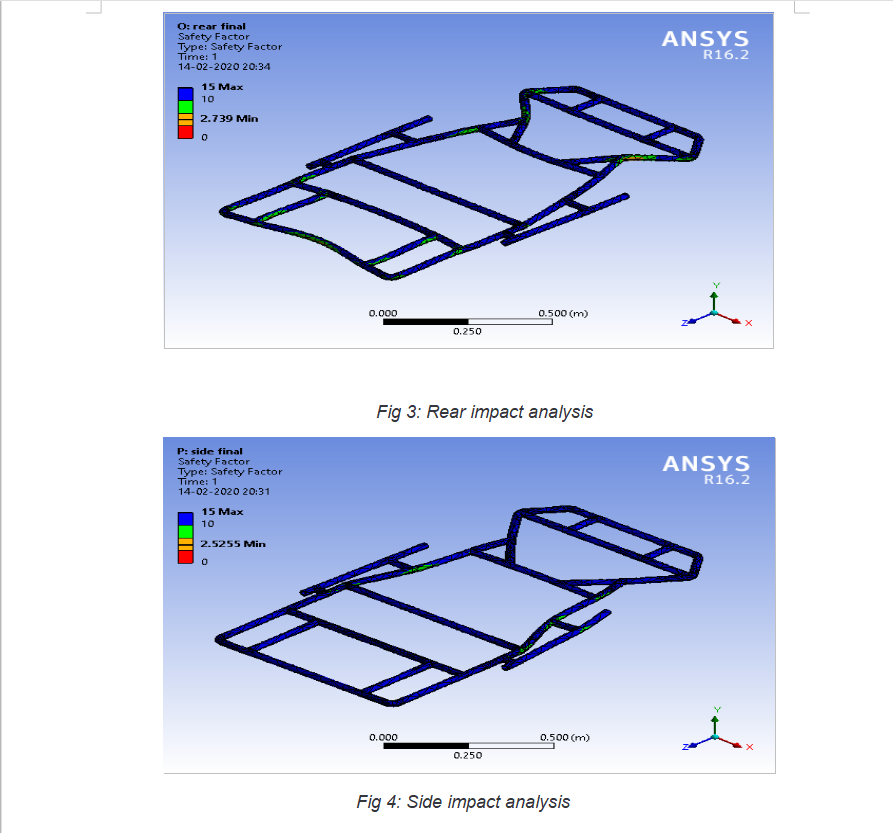
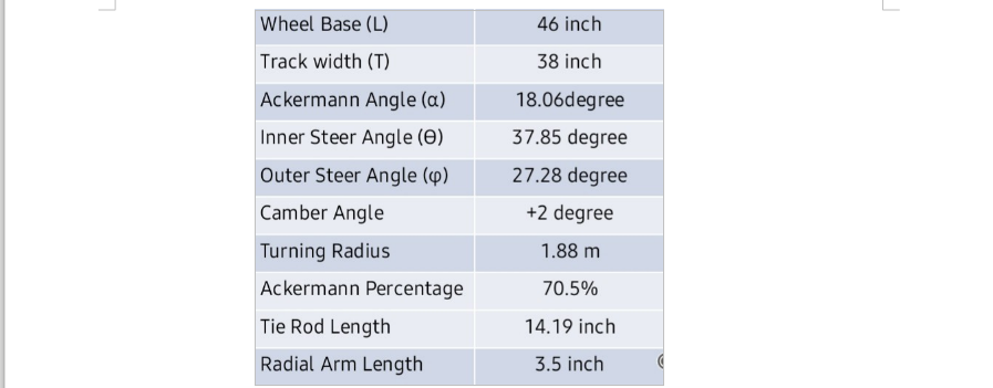
1.1(C): IMPACT ANALYSIS:
• The impact analyses were performed in ANSYS V 16.2. The model is subjected to 6.37 G load force for front and rear impact analyses and 4 G load force for side impact analysis.
• Acceleration= velocity/time = 12.5/0.2= 62.5 m/sec2
= 6.37*9.8 m/sec2
= 6.37 G (where G is acceleration due to gravity)
• Force= m*a= 190*6.37 G=11860 N (For front and rear impact)

• Material used for the frame is AISI 4130 because of:
◦ High fatigue and tensile strength
◦ Low density
◦ Productive in relation to its cost
• Cross section of members used:
◦ Outer diameter = 25.4 mm
◦ Wall thickness = 1.65 mm
• The welding process implemented is Shielded Metal Arc Welding (SMAW)

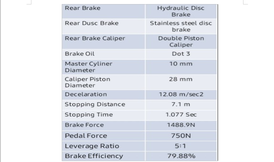
1.2 STEERING:
• The steering system selected was mechanical steering system. In this steering system no steering gear is present and the steering ratio is taken as 1:1. The motion is transmitted from the steering wheel to the wheels via steering linkage system.
• The Ackermann steering mechanism is a geometric arrangement of linkages in the steering of a vehicle designed to turn the inner and outer wheels at the appropriate angles.
• Positive camber creates more tire contact patch, leading to more grip. A 2 degree camber is considered, as more camber may create a loose rear-end of the kart. Camber is applied by moving the king pin bolt or stub axle inward or outward.
• Caster is increased by moving the king pin bolt backward which increases weight transfer to the front. Which essentially gives more positive front-end feel by releasing the back-end of the kart. Positive caster is recommended and it is in the range of 5-10 degree.
• Weight at Front axle (Wf) = W*0.4= 744.8 N
• Tire Cornering Stiffness for Front tires (Cf) = Wf*0.4*(1/2)*0.165
= 61.446 kg/degree
Wf/Cf =12.12 degree/g
• Weight at Rear axle (Wr)= W* 0.6= 1117.2 N
• Tire Cornering Stiffness for Rear tires (Cr)= Wr*0.6*(1/2)*0.165
= 92.169 kg/degree
Wr/Cr =12.12 degree/g
• Wf/Cf=Wr/Cr (Hence Neutral Steer is achieved.)
• Distance between King pin centers, C= 30 inch
• Ackerman Angle (α) = tan-1(0.5*C/L) = 18.06 degree
• TURNING RADIUS, R= L/2 sinα = 74.19 inches = 1.88 m
• Outer Steer angle (ϕ) = tan-1 (L/(R+(C/2))) = 50/(82.27 +16) = 27.28 degree
• Inner Steer angle (ϴ) = tan-1 (L/(R-(C/2))) = 50/(82.27-16) =37.85 degree
• Ackermann percentage:
• ϴ100% = tan-1 (L/((L/tan(ϕ))-T))-ϕ = 14.65 degree
• % Ackermann = (ϴϕ)/(ϴ100%)= 70.5%

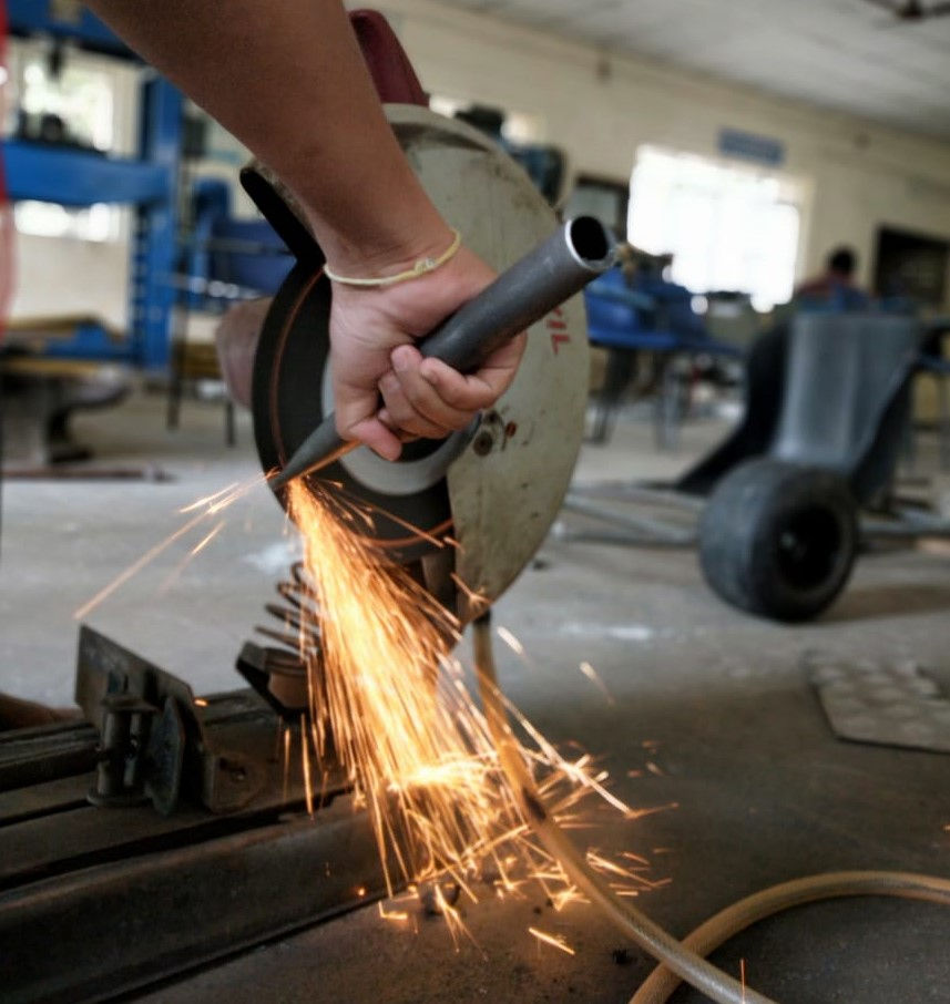
1.3 BRAKES:
The Braking system used is Disc Brake. It is a brake that operates by the action of a frictional material pressed against the sides of a rotating disc by a calliper.
The general equation for braking performance was obtained from the Newtons 2nd law written for the x-direction.
The results were obtained using the given equation:
Max = −W/g∗Dx=−Fxf−Fxr−DA−Wsin(∝)o Where, W = Vehicle weight
Dx = Linear deceleration Fxf= Front axle braking force Fxr= Rear axle braking force DA= Aerodynamic Drag
∝=uphill grade
fs= front axle static load
rs= rear axle static load
h= height of center of gravity
Weight of vehicle with driver=190 kg Wheel base(L)=46 inch
Weight distribution=40:60
Wf/Wr= 40/60 Wf=40*190/100=76kg Wr=190-76=114 kg
Let B be the distance from C.G to Front Axle Let C be the distance from C.G to rear axle
Therefore B= (76/190) *46 *25.4= 467.36mm C= (1168.4-467.36) =701.04 mm
Height of C.G =116.12 mm Deceleration, Dx=(Fxmf+Fxr)/M
= (1008.6+480.6)/190 = 12.08 m/sec2
Where,
• Stopping distance, SD = v2/2Dx = 7.18 m
• Stopping time, ST = V/Dx =1.725 sec Total braking force = Fxmf+Fxr=1256.9 N
Braking Efficiency = 1488.9/ (190∗9.81) =79.9%
Stainless steel is selected as the material for brake disc and caliper which fulfill the mechanical property requirements and with low price.
Properties that are expected with a brake disc for smooth operation are:
• Wear resistance
• Compressive strength
• High thermal capacity and low thermal expansion
• Abrasive resistance
• Capacity to bear high mechanical and thermal stress.
1.4 POWERTRAIN:
Selection Procedure:
Chain drive gives the advantage of more power compared to other systems, they have low maintenance cost and high transmission efficiency.
The motor was selected using the below equation:
• F=Fr + Fd +Fg
F= 41.005+23.9+74.42=139.32 N
• F= Total traction force required
Fr= Frictional force, Fd= Drag force, Fg,= Gradient force
• Tractive force available at wheel (Ft)= Motor torque*efficiency*gear ratio/ wheel radius = 585.8 N
Ft > F. Therefore, our selection is justified.
• Torque T= F*Radius of wheel
• Power Required P=T*w = 1922 W
Hence, the BLDC motor of capacity 2.5 kw was selected.
Maximum velocity= motor RPM * gear ratio* wheel circumference= 69 kmph
• Battery capacity is determined as follows: V*I=P
48*I=2500 I= 52 A
Where, 1.5 hrs is the time taken for discharging the charge. Capacity= 3750/48=78.125 Ah
Where, 1.5 hrs is the time taken for discharging the charge. Capacity= 3750/48=78.125Ah
Therefore, the desired capacity is 80Ah.
Based on the availability and compatibility with the wheel, we have selected the chain sprocket set of TVS APACHE RTR 180
• Number of teeth on Driven Sprocket=46
• Number of teeth on Driver Sprocket=14
• Sprocket (or) Gear Ratio(G.R)=46/14=3.28 Traction Force available at the wheel(Fx) is
Fx =( motor torque* efficiency of transmission* gear ratio)/ wheel radius
=( 8 N-m * 0.9* 3.28)/0.134
= 176.3 N
Since the Tractive Force available at the wheel is greater than Tractive Force required(F) , our selection is justified.
1.5 : MODIFICATIONS:
Several modifications have been performed after the submission of the virtual document according to the reviews given by the experts and also for making the better of the kart, these are as follows:
• The wheelbase is changed from 52 inches to 46 inches considering the driver's comfort and also making the kart to perform well.
• The steering parameters( turning radius, Ackerman angle, Ackerman percentage etc) are changed due to the change in wheelbase and those changed values are updated in the steering subsystem calculations (Refer 1.2 paragraph)
• The track width is changed from 40 inches to 38 inches.
• The factor of safety values are updated according to the reviews given by the experts panel of NEKC.
• Initially, along with 48 V Lithium ion battery, a 12 V Lithium ion battery was also considered for supplying power to auxillaries like horn, lights etc but due to increase in the cost of the overall budget, the thought of using 12 V battery was removed.

• The thermal analysis for the disc brake is conducted by considering both grey cast iron and stainless steel materials and it was found that the rate of heat transfer was higher in stainless steel than that of in grey cast iron.
• Therefore, the disc brake made of stainless steel is considered.

Comments